
Installation guide
Installing SavvyVan3
Two parts to fit: a control board that screws to a flat surface, and a touch screen that goes wherever you want to look at it. Between them is a 2m HDMI and USB cable - standard parts, so longer ones are easy to buy. Take your time over the screen cut-out and the rest is straightforward.

At a glance
- Two parts
- Control board and touch screen, 2m of cable supplied
- Board size
- 180 × 105 × 27 mm, screwed to a flat surface
- Supply
- 12V and 24V systems, up to 30V. 2A fuse built in
- Switches
- 8, up to 10A each, positive or negative
- Screen cut-out
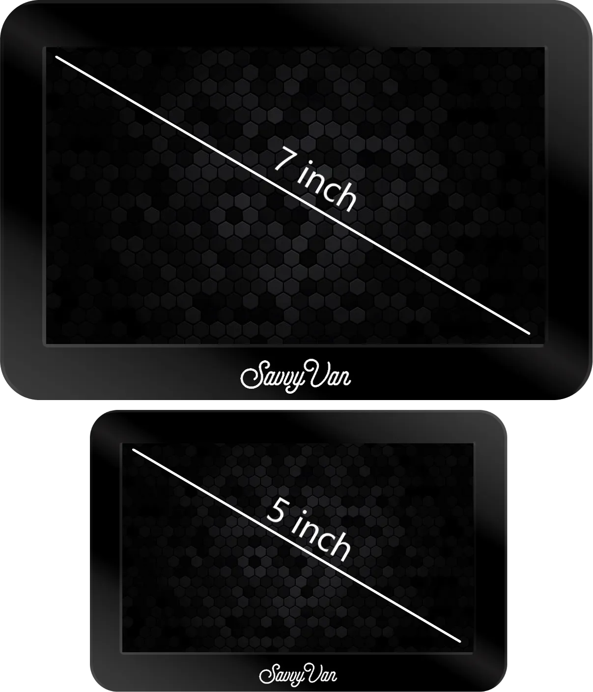
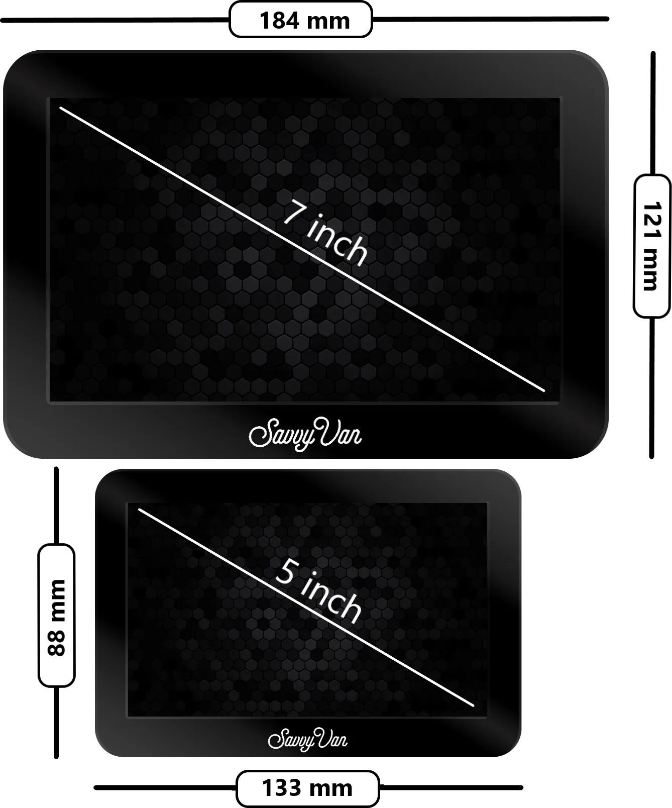
- 123 × 79 mm for the 5", 166 × 102 mm for the 7"
- Behind the screen
- 18 mm clearance, or 40 mm with 180° adapters
- Operating temperature
- −20°C to +60°C
Watch it first, if you would rather
Seven minutes of the whole job - what is in the box, mounting and wiring the board, and the first power-on. Watch it before you cut anything.
Before you start
It must be installed by a suitably qualified person, such as an auto electrician - our terms say the same, and this is not the job to learn on. If you would rather not fit it yourself, our installers will.
Test it before it goes near a wall. Put the unit on a 12V bench supply and check it starts. If anything looks wrong, email support@savvyvan.com before fitting - half of it ends up bonded in place.
Register your device once it is in. The SavvyVan3 carries a 12-month warranty, and registering it inside that year adds a second one free.
Planning it out
The panel is two parts, joined by 2m of HDMI and USB cable. Give each position five minutes with a tape measure before you cut - and if 2m is short, longer cables are easy to buy.
The control board is 180 × 105 × 27 mm and screws to any flat surface. Leave three sides clear for cabling, keep it reachable - it is a serviceable part, more below - and put it within cable reach of the battery and the appliances you are switching.
Think about signal while you choose the spot. The wireless lives in the control board, not the screen, so this position decides whether WiFi reaches and whether the add-ons stay connected. The case is plastic and blocks nothing; the van does. Foil-backed insulation, a spot behind the fridge, or a steel wall between the board and the rest all cost you range - and you cannot get it back once the panelling is on.
The touch screen is 15 mm deep, plus room behind for cables - 18 mm clearance, or 40 mm if you are using 180° adapters. On a hard surface the visible profile is just 1.2 mm.
If 2 metres is not far enough
Our most common question, and the answer is a good one: the cables are standard parts, so you can buy longer ones anywhere. Nothing about them is special to us.
What you need is:
| Picture | HDMI to HDMI mini |
| Power and touch | USB micro to USB micro |
Those exact cables are awkward to find in longer lengths, so most people buy the ordinary version - HDMI to HDMI, and USB to USB micro - and add an adapter. That works fine.
We do not recommend a brand - we would rather say so than point you at something we have not tested. Any decent cable of the right type is fine.
Mounting the control board
The control board is a serviceable part. It must be mounted where it can be reached, disconnected and removed without dismantling fixed furniture, bonded panels or the touch screen - for example in an electrical locker, under a seat, or behind a removable access panel. Use the 2m cables to position it away from the screen where needed. Do not mount it in a sealed or unventilated space, or near heat sources.
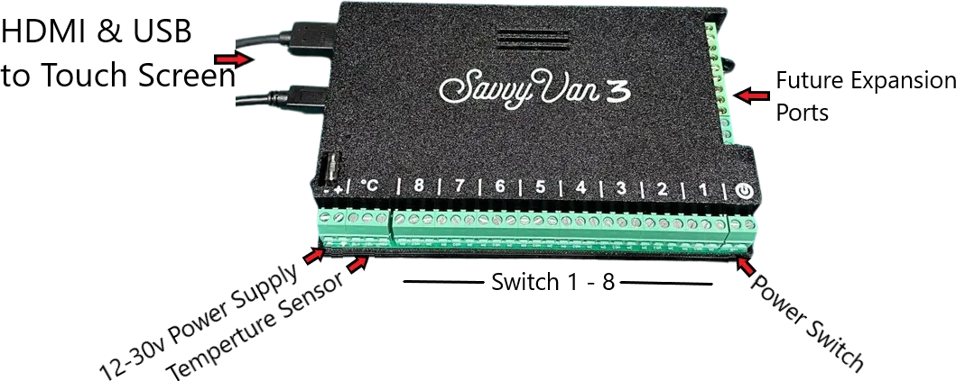
Screw it to a flat surface with enough clearance to get cables into three sides. It needs three connections:
- Power. 12V or 24V to the terminals marked +/−. There is a 2A fuse built in. In operation it draws 0.1–0.3A at 12V.
- Temperature sensors (optional). Several can share the same port.
- One side of each appliance you want to switch - positive or negative, your choice. The board works as an inline toggle in the circuit.
The power switch
The power switch terminals are a signal line, not a power feed. Bridging them briefly tells the panel to start up or shut down. A momentary - non-latching - push button is the usual way to wire it.
The power icon at the top right of the screen is not this switch. It turns the display off and nothing else - every circuit stays as it was, and a touch wakes it again.
The second voltage input
The board has a second voltage input, which puts a second dial on the screen - usually for the starter battery, so the owner can see whether the van will start. On the board it is the second screw terminal down on the right-hand side.
It is off until you switch it on: Installer Settings → Battery Settings, then tick Enable Secondary Sensor, top right. A second battery, with a van drawn on it, appears on the home screen under the first, reading in volts. The user guide explains it to the owner. Fine Tune Voltage on the same page adjusts both inputs together - more on that page below.
Switching appliances
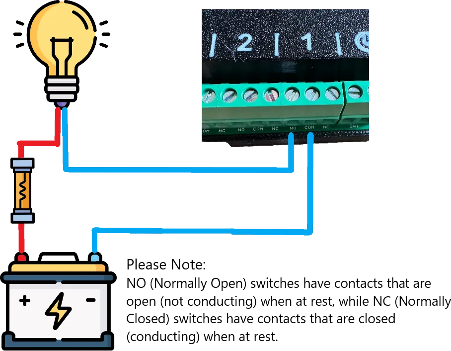
Each of the eight switches handles up to 10A, and each can switch either the positive or the negative side of a circuit.
There is no fusing on the switched circuits - every circuit you run through the panel needs its own fuse.
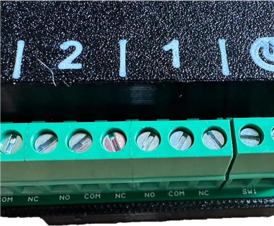
Each switch has three terminals:
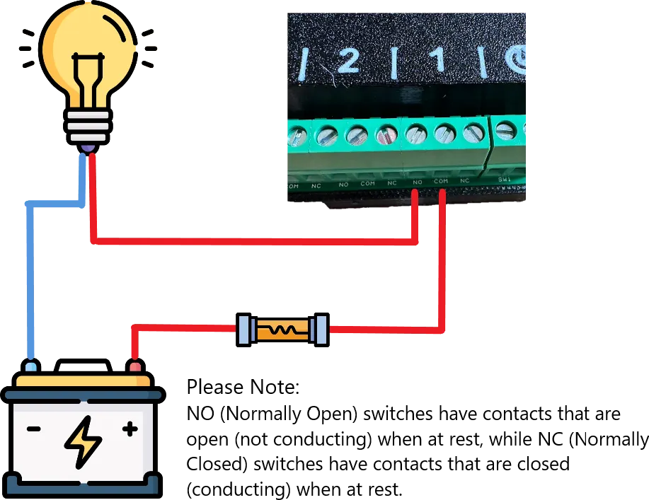
- COM - the feed in.
- NO (normally open) - appliance off by default, panel switches it on. This is what most people want.
- NC (normally closed) - appliance on by default, panel switches it off.
Positive switching
Connect the appliance directly to ground. Battery positive goes through a fuse into COM. The appliance’s positive goes to NO, or NC if you want it on by default.
Negative switching
Connect the appliance’s positive through a fuse to the battery. The negative from the battery goes into COM, and the appliance’s negative to NO - or NC for on-by-default.
More than 10A
Anything over 10A needs an external high-current relay, driven from one of the switches. Wire the relay per its own instructions; the panel only provides the signal.
Kit with its own on/off input
Some kit has a remote on/off input of its own, and a switch drives it with no feed at all: wire the input’s two terminals to COM and NO, and the switch simply joins them. A Victron MultiPlus-II works this way, and has its own guide.
Temperature sensors
Switch the unit off first. Then wire the supplied sensor into the screw terminals marked °C, matching the colours:
- BLK to black
- YEL to yellow
- RED to red
Several sensors can share the port. Indoors, use the supplied mount and pick a spot with an even temperature - not above a heater or against a cold outer wall. Extra sensors are on the shop.
Once the panel is running, tell it which sensor is where - it cannot tell inside from outside on its own. That is in Additional settings, further down.
Mounting the touch screen
Best results come from bonding the screen directly to a hard surface with the supplied VHB high-temperature tape.
5 inch
Adhesive only, because of its size.
- Cut an aperture of 123 × 79 mm in a hard surface, with at least 18 mm clearance behind for cables - 40 mm if you are using 180° adapters.
- Connect the cables, and any adapters you need.
- Test the unit fully. This is the last easy moment.
- Clean the surface, then peel the tape and press it into place.

7 inch
Three options: adhesive, or a mounting plate screwed or bolted on. Adhesive gives the lowest profile; bolted is the only one you can undo. The plate is an optional extra, not in the box - order it with the screen, because afterwards is too late.
Adhesive
- Cut an aperture of 166 × 102 mm in a hard, flat surface, with at least 18 mm clearance behind.
- Connect the cables and any adapters.
- Test the unit fully.
- Clean the surface, peel and press.
Mounting plate
- Use the plate as a template to cut the correct aperture.
- Drill for the bolts if you are bolting it on.
- Test-fit before committing.
- Attach the plate to the wall.
- Connect the cables to the screen, and any adapters.
- Test the unit fully.
- Clean the plate and bond the screen to it.

First startup
The panel starts as soon as the 12V supply is live. Give it up to 60 seconds to calibrate on the first run, including a few seconds of black screen after the logo - it is not stuck.
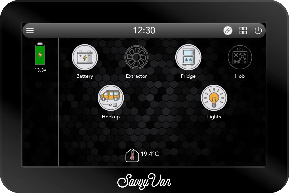
Update it before you configure anything. New features and fixes land regularly, and starting from the current version saves redoing settings.
Not coming up? Troubleshooting, at the bottom of this guide, narrows it down in a few minutes.
Connecting to WiFi
WiFi is needed for the clock, the weather widget and updates - everything else works without it. Use the 2.4GHz band where you have the choice: it reaches further than 5GHz, and range is the limitation here, not speed.
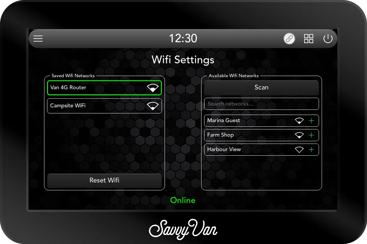
- Tap the menu top-left and select Wifi. The page looks for networks as it opens, and Scan looks again.
- Under Available Wifi Networks, tap your network - the one with the green + beside it. With a long list, Search networks… narrows it down.
- Enter the password and tap Save.
It joins after a few moments and moves across to Saved Wifi Networks, where the network it is connected to has a green border and a symbol for its signal strength. The foot of the page says Online in green once it reaches the internet, Wifi Connected - No Internet in orange when it is on a network that is not getting out, and Offline in red when it is not connected. To forget a network, tap it under Saved Wifi Networks and choose Delete.
Getting into the settings
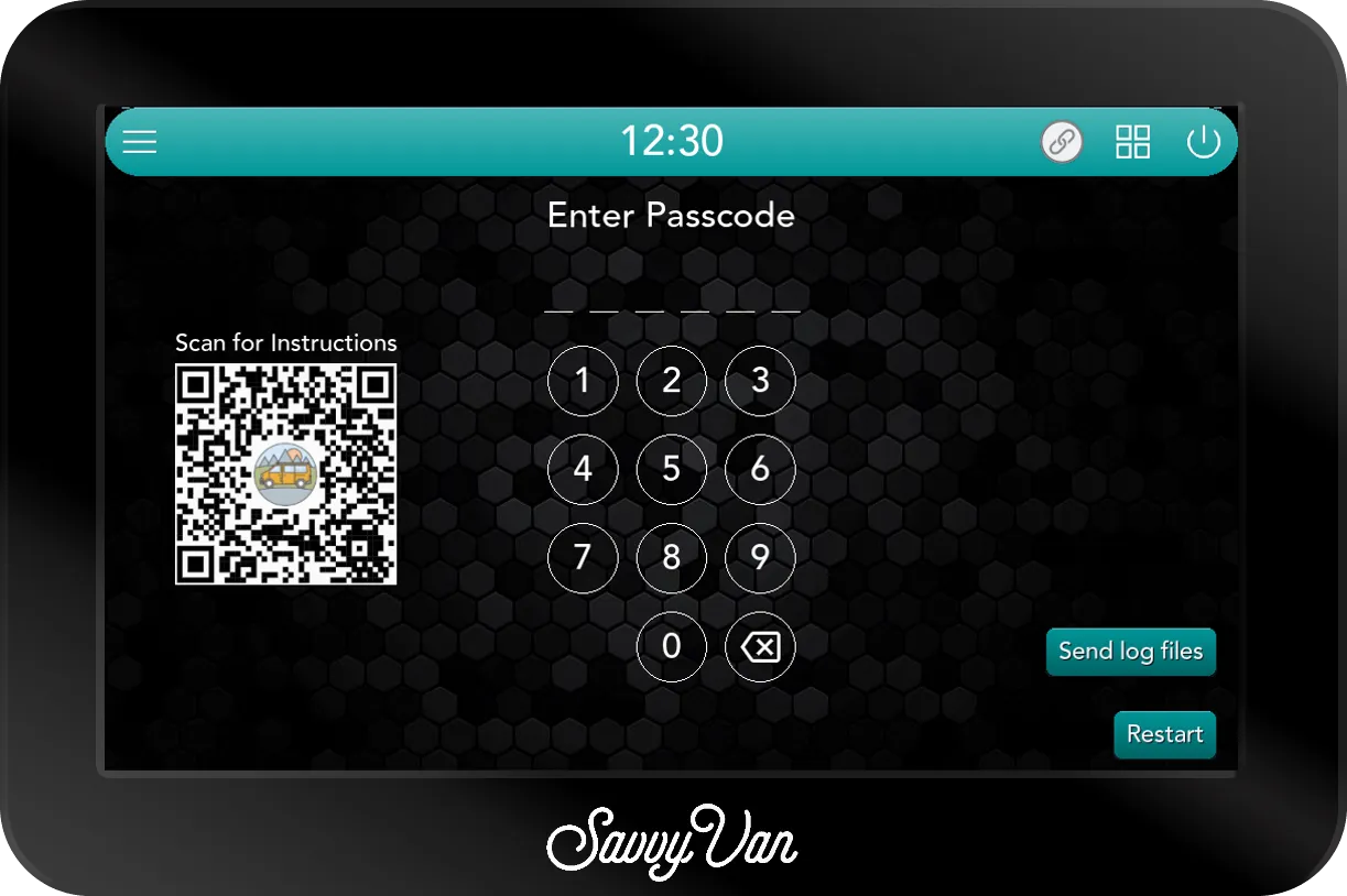
Tap the menu, then User Settings or Installer Settings. The default passcode is 123456 for both, unless an installer set their own - if you bought the van or panel second-hand, ask them.
From this screen you can also send log files back to us if something is misbehaving, and restart the panel.
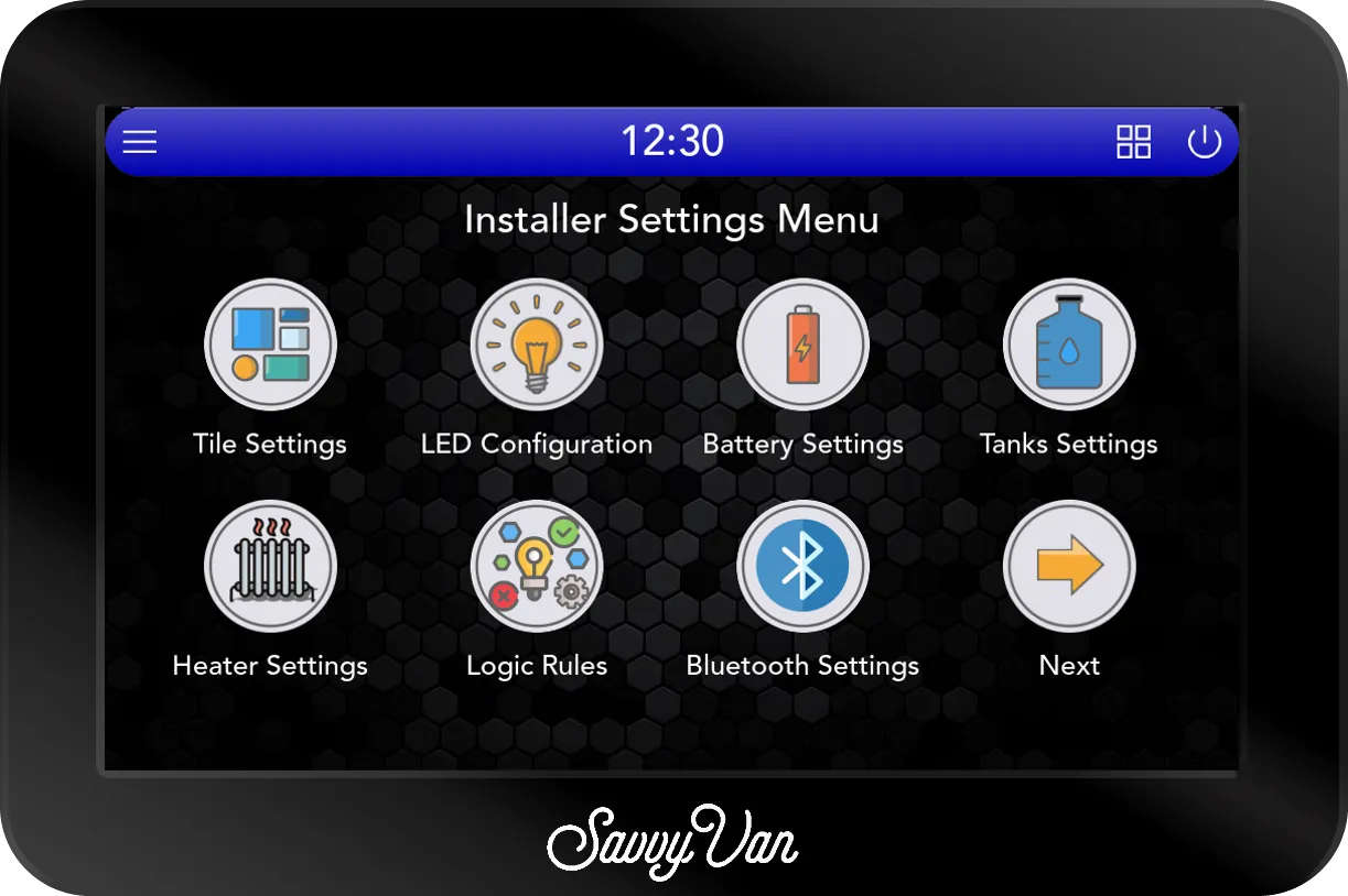
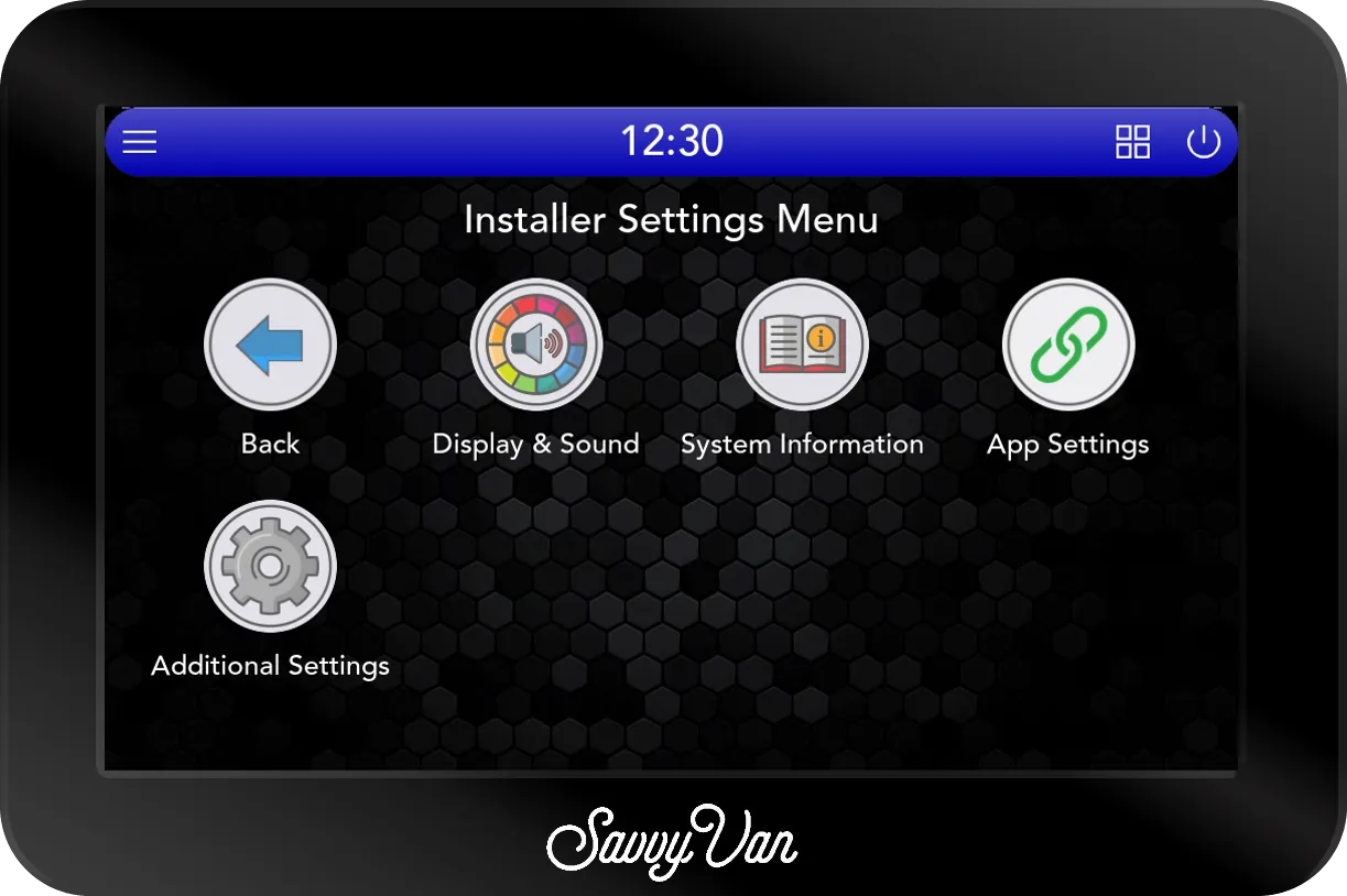
Installer Settings is where the panel gets set up, and the menu runs to two screens: Next, bottom right, turns the page, and Back returns to the first. The back arrow top-left of any settings page brings you back to the menu.
User Settings is the owner’s shorter menu: Display & Sound, System Information, App Settings, Water Heater Settings, and the lists of paired devices and logic rules. Nothing that decides how the van is wired is in it, so the owner cannot undo your work by accident.
Every page, and where it is covered
Work down this list in order and the panel is set up. Every page has its own section further down this guide, with every setting on it - tap its name to jump there.
| Page | What it sets |
|---|---|
| System Information | Updates, and the serial number and versions we ask for |
| Tile Settings | What each of the eight switches is called, its icon, and which one is a water heater |
| Logic Rules | One tile switching another, so two things go on or off together |
| Additional Settings | Which temperature sensor is inside and which outside, the weather, and Starlink |
| The pairing page, last on the first screen | Adding wireless add-ons, and a battery the panel reads directly |
| Battery Settings | How the panel reads the battery, the second voltage input and the low voltage cut-off |
| Tanks Settings | Which tanks you have, their sizes, and which valve each one opens |
| Heater Settings | Which heater is fitted, and its automatic modes |
| LED Configuration | Which lighting channels you used, their names and your scenes |
| App Settings | The phone app’s pairing code, its icon in the top bar, and resetting the pairing |
| Display & Sound | Colour, tap sounds, the wake-up screen, how long the screen stays on, and the date and time |
Updating the panel
- Make sure you are on WiFi with a decent signal.
- Open System Information from the settings menu.
- Tap Update Now.
If there is an update, it installs and restarts. The screen may be blank for up to 10 minutes while it does - leave it alone. The button reads Updating … while it checks, and a panel that is not online says Device is offline. Connect to wifi to update. instead.
The same page shows what we will ask for first if you contact us:
- Device serial number.
- Appliance version, Hardware version and Software version.
- Connected Devices - the serial numbers of the add-ons we have on record for this panel.
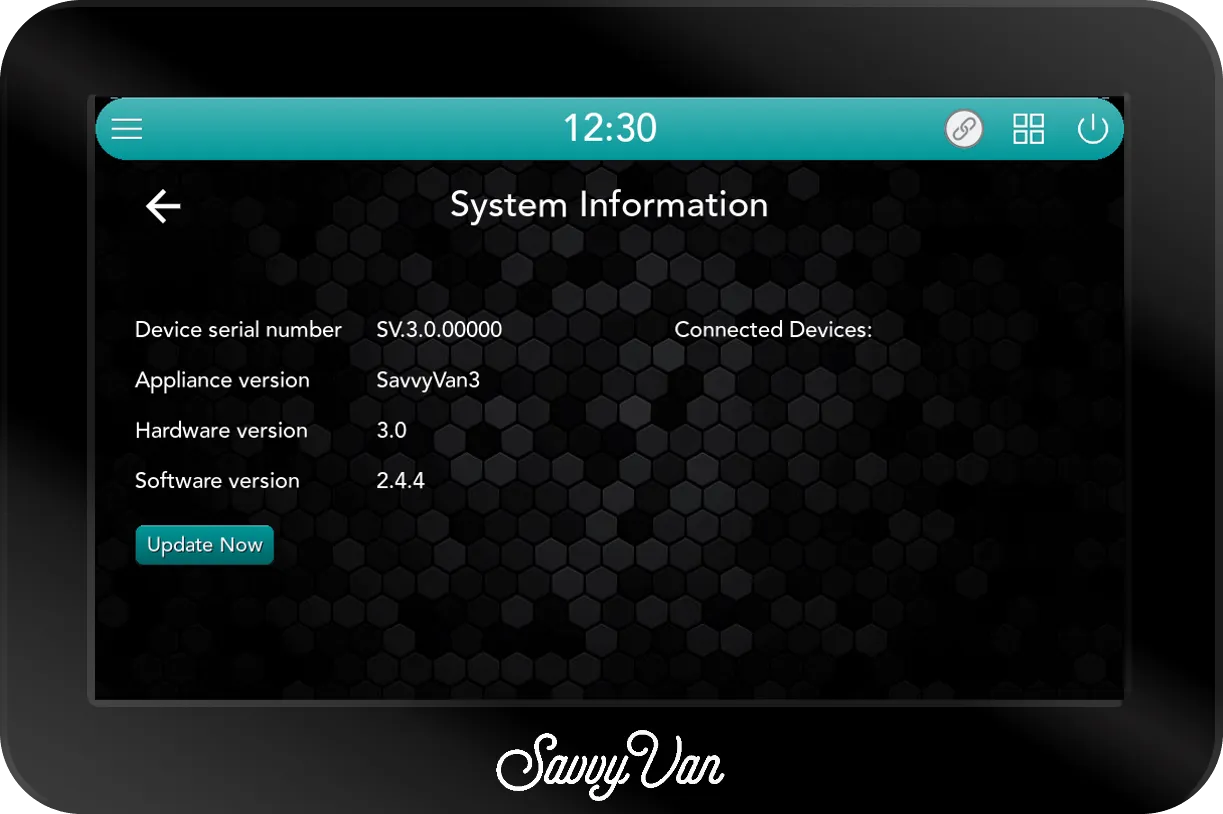
We announce releases by email if you are on the mailing list, and every change is listed in the changelog.
Configuring your tiles
Tiles are the buttons on the main screen, and each one maps to a switch you wired: switch 1 is tile 1, and so on.
- Go to Installer Settings → Tile Settings.
- Choose how many tiles you have connected.
- Select a tile to configure it.
- Tap the icon on the right to see the full set, using the arrows to page through, and pick one.
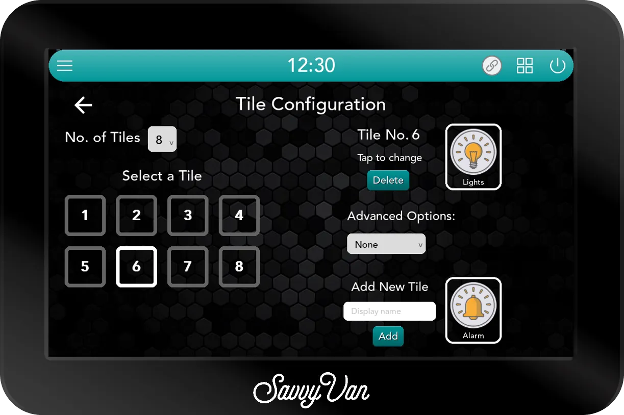
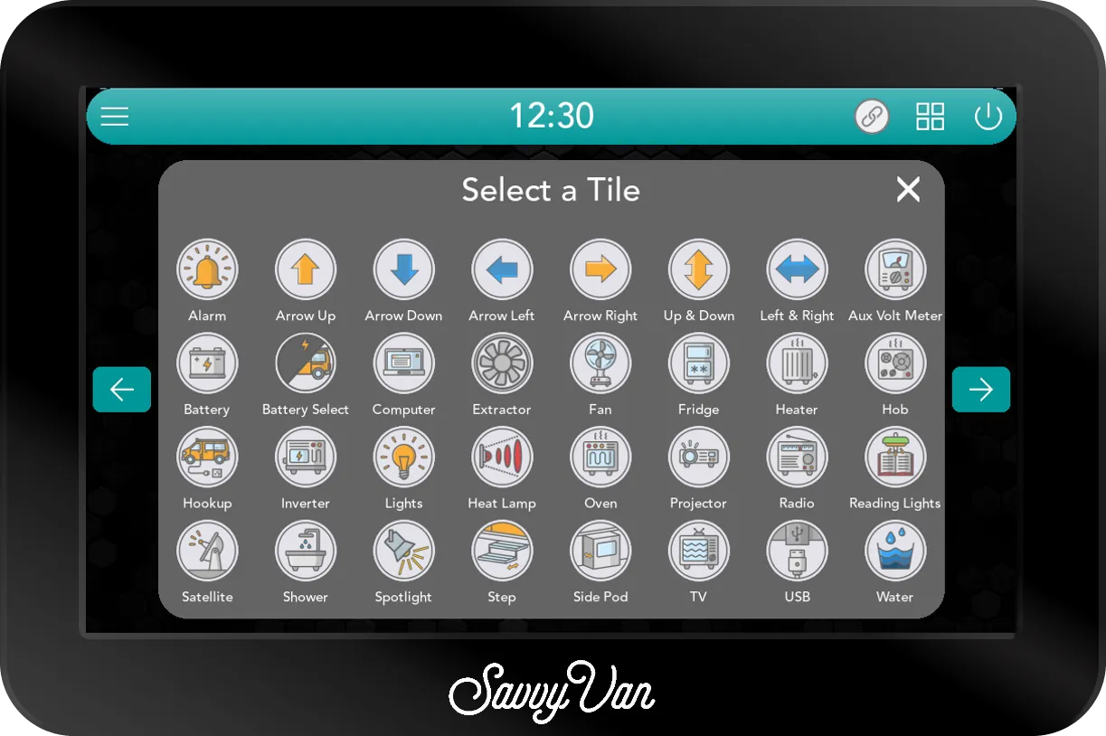
A tile that does not exist yet: type a name into Add New Tile, choose an icon, and tap Add. It joins the picker like any other. To remove one you made, select it and tap Delete.
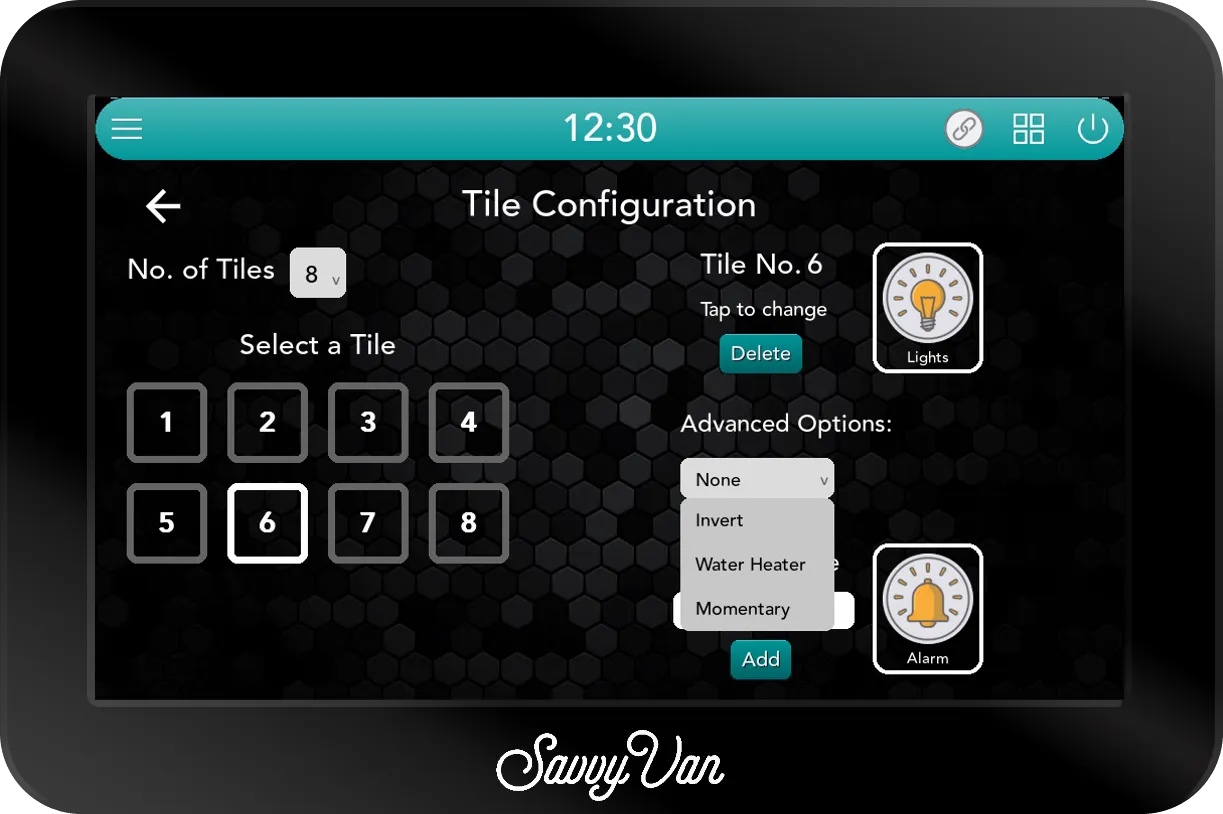
Advanced options for a tile
- Invert flips the icon’s on and off states - useful when a circuit is wired normally-closed, so the screen shows what is actually happening rather than the opposite.
- Momentary makes the tile live only while your finger is on it. Press and hold to run, let go to stop.
- Water Heater turns the tile into a managed water heater, with a schedule, an auto-off delay and battery protection behind it - a cog appears beside the dropdown, and its page is below. Only one tile can be the water heater, so choosing it for a second clears it from the first. Wiring a Pundmann heater to a switch through a relay is in its own guide.
They are all in the Advanced Options dropdown, which starts on None.
Water Heater Management
The cog beside a Water Heater tile opens this page. Everything on it acts on that one tile, and does nothing until a tile is set to Water Heater.
- Enabled - the switch for everything automatic below. It starts ticked. Tapping the tile on the main screen works either way.
- Schedule - an On time, in 15-minute steps, and a tick box for each day from Mon to Sun. The heater comes on at that time on the ticked days. It starts at 08:00 on Monday and Tuesday.
- Auto off delay - Off, 30, 60, 90 or 120 minutes. However the heater came on, by hand or on the schedule, it goes off again that long after. It starts at 90.
- Charge Overflow - the heater comes on when the battery reaches 95% and goes off again at 90%, so it spends charge that would otherwise go to waste. Ticking it sets the auto off delay to Off. It starts unticked.
- Auto Off - the heater goes off when the battery drops to this, in 5% steps. It starts at 20%.
Charge Overflow and Auto Off need a battery percentage, so they are greyed out and do nothing unless a SavvyShunt or a battery the panel reads directly is paired.
The owner has this page too, as Water Heater Settings in User Settings, so it is theirs to adjust once the van is handed over.
Logic rules
A logic rule ties one tile to another: when one tile is switched on or off, the panel switches a second tile on or off for you. The fan that comes on with the hob, say, or the pump that goes off with the lights.
- Open Logic Rules, on the first screen of the menu, and tap Add New Rule.
- Under Trigger, choose the tile to watch and whether it is switched on or off.
- Under Action, choose the tile to switch and whether it goes on or off.
- Tap Submit. The rule joins the list on the Logic Rules page.
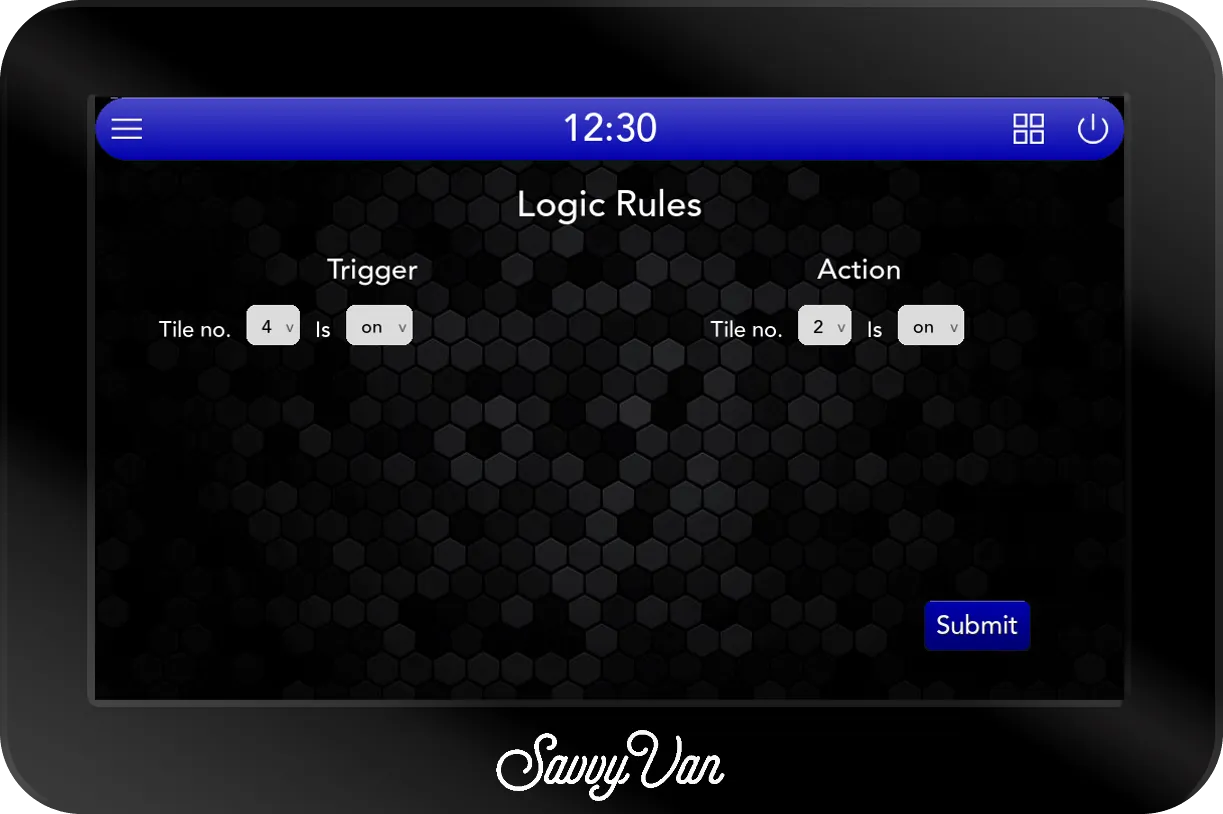
A rule acts once, at the moment the first tile is switched. It does not hold the second tile there, so either can still be switched on its own afterwards. If both should also go off together, add a second rule for that.
The two tiles must be different - the panel says so if they are not. To remove a rule, tap the delete icon beside it in the list; it goes straight away, with no question first. The owner sees the same list in User Settings but cannot add or remove rules.
Additional settings
On the second screen of the menu. Three things live here, and the first is worth doing on every panel.
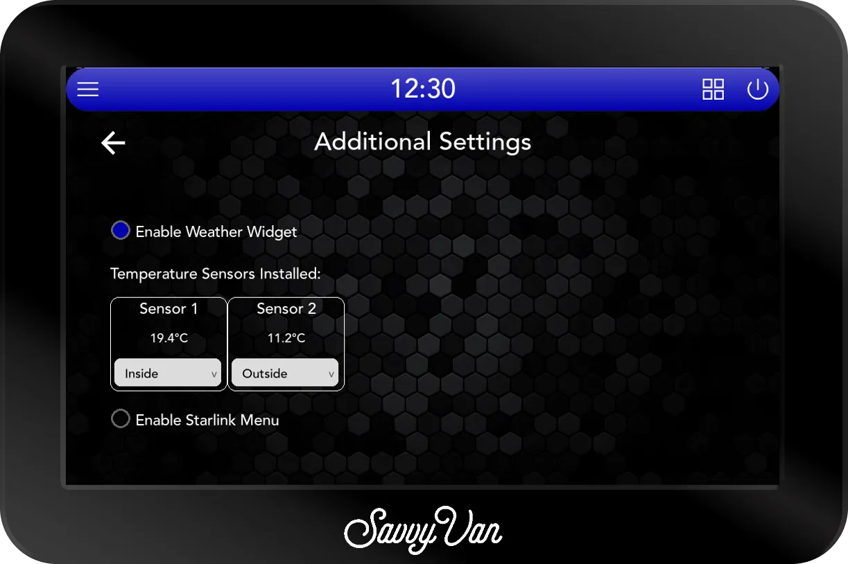
Temperature Sensors Installed. Every sensor on the °C terminals gets a box - Sensor 1, Sensor 2 and so on - with its reading underneath. A new sensor does not know where it is, so use the dropdown under each one:
- Inside - the temperature in the van.
- Outside - the one on the outer wall.
- Water Heater - a sensor on the water heater, if you fitted one there.
- None - fitted, but not shown.
Each place takes one sensor. Give a second sensor a place that is already taken and the first one goes back to None.
Not sure which box is which sensor? Hold one in your hand for a minute and watch which reading climbs.
Enable Weather Widget puts the five-day forecast along the foot of the main screen. It starts ticked. It needs WiFi, and it does not appear while the panel is offline.
Enable Starlink Menu adds a Starlink page to the side menu, for a van with a dish. It starts unticked, so a van without one has no empty page, and ticking it puts the page in the menu straight away. What the page shows is in the Starlink guide.
Customisation ID appears only on a panel built to a customer’s own branding. Leave it alone unless we have given you an ID to enter - it is part of a trade build, not something to change on site. Deploy fetches that customer’s own set-up for the panel, which needs WiFi, and restarts the panel 30 seconds after it lands.
Pairing add-ons
Every wireless add-on is added the same way, and so is a battery the panel reads directly. It all happens on the pairing page, the last icon on the first screen of the menu. Once it is open, Scan is on the right.
- Power the add-on first. Each add-on’s guide says what its light shows when it is ready to pair.
- Tap Scan, and give it a few seconds to look around.
- Tap the green + next to the add-on. It moves across to the saved list on the left.
- Wait for the symbol beside it to turn blue. That means it is connected.
Each result shows its signal as Good, Fair or Poor. Poor is worth fixing now, by moving the add-on or the control board, rather than once the panelling is on. With a long list, the search box above it filters by name.
In the saved list, a SavvyShunt, SavvyTanks or SavvyLights has a cog beside it that goes straight to its settings page - Battery Settings, Tanks Settings or LED Configuration. The delete icon beside any device removes it at once, with no question first. Pairing a SavvyShunt or a battery also sets Shunt Type in Battery Settings for you.
What each add-on is called in the list is below. Its own guide covers wiring it and what its light shows when it is ready to pair:
| Add-on | Listed as | Its guide |
|---|---|---|
| SavvyShunt | SavvyShunt | Pairing it |
| SavvyTanks V3 | TanksV3 | Pairing it |
| SavvyLights | LED_V1 | Pairing it |
| SavvyStance | StanceV2 (SavvyStance on a first-generation sensor) | Pairing it |
| Propex heater module | PropexV2 | Pairing it |
| Autoterm heater module | AutotermV1 | Pairing it |
| A battery read directly | Its own name, by make | Each make has a guide, listed under Power |
Battery settings
Installer Settings → Battery Settings - the page is headed Battery Management - tells the panel how it reads the battery. Shunt Type is the choice: Voltage Sensor for the panel’s own sensor, SavvyShunt, or Direct to BMS for a battery that talks to the panel itself. The rest of the page changes to suit. None of it is in User Settings, so the owner cannot change it by accident.
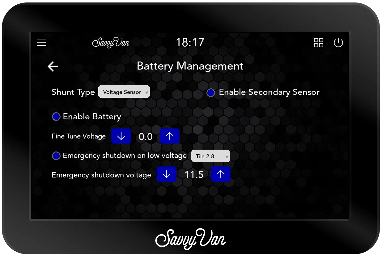
Whatever the Shunt Type, Enable Secondary Sensor, top right beside it, is the second voltage input. It starts unticked.
On Voltage Sensor:
- Enable Battery puts the voltage dial on the home screen. It starts ticked; untick it and the rest of these settings disappear with the dial.
- Fine Tune Voltage nudges the reading up or down in 0.1V steps, if it disagrees with a meter you trust. It applies to both voltage inputs.
- The low voltage cut-off, below.
Low voltage cut-off
The panel can drop circuits on its own before the battery gets too flat. It is off when the panel arrives, and worth two minutes of setting up. Three controls:
- Emergency shutdown on low voltage - the tick box that arms it.
- A dropdown for what it switches off: All Tiles, Tile 1 only or Tile 2-8. It starts on None, and on None nothing happens however low the battery goes - so this is the one people forget.
- Emergency shutdown voltage - the figure it acts on, in 0.1V steps. 11.0V to start with.
Tile 2-8 is the usual choice: it sheds everything but the first circuit, so whatever is on tile 1 stays up. Below the figure you set, those relays open. It acts once on the way down and re-arms as soon as the voltage recovers, so a battery hovering around the number will not chatter.
When it acts, the owner gets a message on screen that also stays in their notifications - the user guide tells them what it means.
On a SavvyShunt
With Shunt Type on SavvyShunt, the page asks for the battery’s Capacity. Enter the capacity you can actually use rather than the number on the battery; the SavvyShunt guide has the figures by battery type. Reset History wipes the battery history.
The usable share of the battery is what goes in, because batteries do not like being emptied: 80% of the total for lithium, 60% for AGM and 50% for lead acid. Type it as a whole number and tap Save.
Battery Charge Offset shows the correction the panel applies, and Reset Offset sets it. Tap it with the battery full: that makes the current reading 100%, and the panel adjusts from there as the battery charges. Do it again after fitting a new battery or moving the shunt. With no shunt paired, the page says No Shunts connected. instead.
Inside the pack
With Direct to BMS and a battery connected, the page shows the battery’s name and its maker’s logo. If the panel does not recognise the name, a Vendor dropdown lets you choose the make from the eight it reads directly. Reset History wipes the battery history. With no battery connected, the page says No Device Connected.
There is also a Battery Data button, and there is more to see than the pack as a whole - as much of it as the battery reports:
- How many cells there are, and the average cell voltage.
- Every individual cell voltage, and the cell voltage delta - the gap between the highest and the lowest, which is the number that matters.
- Whether the balancer is working, and how hard.
- Cell resistances, the pack’s temperature sensors, and its state of health and charge cycles.
All Data and Cell Details, along the bottom of the box, swap between the full table and the cell-by-cell grid. On a battery that does not report its cells one by one, Cell Details is greyed out.
Most of the time nobody will open it. It earns its place when a cell starts drifting from the others, which is usually how a lithium pack begins to fail - and you can see that on the van’s own screen instead of needing a laptop and the battery maker’s app.
A shunt cannot show any of this. It measures from outside the battery, so it knows what is going in and out and nothing about what is happening inside.
Your add-ons’ own pages
Three pages on the menu belong to an add-on, and each is set up in full here. Leave any page for an add-on the van does not have. Wiring and pairing each add-on is in its own guide.
Tanks Settings
The page is headed Tanks Configuration. What sits at the top depends on the panel:
- A standard SavvyVan3 has an Enable switch. Turn it on for SavvyTanks.
- A Sargent, CBE or BCA version has a dropdown in its place - Disabled, SavvyTanks or Onboard - because those panels can also read the van’s own water sender. Onboard is that sender. We switch it on before a panel leaves us, so a standard panel only has it if we set it up for an onboard sender.
With SavvyTanks, the page has a column for each tank: Water Tank 1, Water Tank 2, Water Tank 3 and Gas Tank. Each has its own Enable switch, and only an enabled tank appears on the main screen. Tanks 1 and 2 and the gas tank start enabled; tank 3 starts off. For each tank you use:
- Type, on a water tank - Fresh Water, Gray Waste or Black Waste.
- Source, on the gas tank - Tanks reads the gas level from SavvyTanks, Propex from a paired Propex heater module. Only the modules actually paired are offered.
- Capacity - tap the box, type the size as a whole number and tap Save. It is what lets the screen show litres as well as a percentage.
- The unit beside it - L or Gal for water. The gas tank reads in Kg.
- Relay - 1 or 2, if you wired a valve to one of the module’s relays. Choosing it here is what makes tapping that tank on the main screen open the valve. A relay belongs to one tank, so choosing it for a second clears it from the first.
The gas tank has no Relay choice with SavvyTanks V3: the solenoid links to the gas tank automatically. Only the older SavvyTanks V2 module shows one there.
With Onboard, choose the sender under Onboard Water Sender Type:
Sargent, CBE_PC100 - the standard CBE probe - CBE_PC200, or
BCA. A CBE version arrives set up already. The onboard sender reads fresh
water only; grey and black water need SavvyTanks alongside it.
A BCA sender measures pressure rather than level, so it has to learn the tank first, and both ways start with the tank empty. BCA sender calibration mode chooses how:
- Automatic, the default - tap Reset with the tank empty, go back to the main screen, and fill the tank. The panel learns the level as it fills.
- Manual - tap Set Empty with the tank empty, fill it, then tap Set Maximum.
Heater Settings
The page is headed Settings. Heater Model is the choice, and pairing the heater’s module makes it for you - so on most vans this is a check rather than a job. On a Propex, check it properly: pick the wrong model and the heater behaves oddly rather than not at all.
- HS2000E - a Propex that runs on gas and electric.
- HS2000 - a Propex that runs on gas only.
- Propex (electric only) - no gas at all. It uses the 3-pin electric cable only, so the gas connector and the solenoid wiring do not apply, and there is no LPG level on screen.
- Autoterm - the diesel heater.
Below the model sit the tick boxes for that model’s automatic modes. Choosing a model sets them to a starting value:
| Model | Its tick boxes, and how they start |
|---|---|
| HS2000E | Enable Auto Electric Mode ticked, Enable Auto Gas Mode unticked |
| HS2000 | Enable Auto Gas Mode unticked |
| Propex (electric only) | Enable Auto Electric Mode ticked |
| Autoterm | Enable Auto Heat Mode ticked |
- Enable Auto Electric Mode adds an automatic setting to the electric element on the heating page. The panel then picks the level itself - higher the further the van is below the temperature asked for, and off once it gets there.
- Enable Auto Gas Mode adds an automatic setting for the gas burner, and has the panel open the gas solenoid when the burner calls for gas and close it afterwards. Unticked, the solenoid is switched by hand, from the gas tank on the heating page.
- Enable Auto Heat Mode is what puts Auto Heat on an Autoterm’s heating page. Leave it ticked.
Whichever heater it is, give the van a sensor set to Inside in Additional settings. It is the temperature the heater works to, and an Autoterm cannot run Auto Heat without one.
The QR code on the page, Scan for Setup Instructions, opens setup instructions on a phone.
LED Configuration
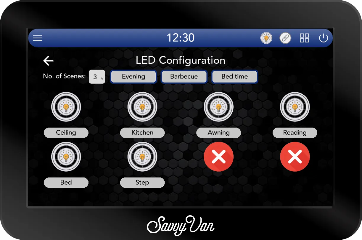
The page for SavvyLights, headed LED Configuration. Pair the SavvyLights module first.
- The eight channels start named One to Eight. Tap a channel’s icon to switch it in or out of use: a light means in use, a red cross means not. Only channels in use appear on the lighting page, so take out any you did not wire.
- Tap a channel’s name to change it - Kitchen, Bed, Awning, whatever you call them out loud. The name shows only while the channel is in use.
- No. of Scenes - how many scenes the lighting page offers, from 0 to 4. It starts at 2, named Barbecue and Bed time; tap a scene’s name to change it. A scene’s light levels are set on the lighting page itself, not here.
App Settings
The phone app pairs by scanning the QR code on this page, under Scan to pair your phone. The owner has the same page in User Settings. On it:
- App Status - App features disabled, No phone paired, Paired, disconnected or Paired, phone connected, with the link icon beside it in grey, orange or green.
- GroupID - the pairing code the QR code carries.
- Show task tray icon - puts the link icon in the top bar, so the QR code is a tap away from any screen. The icon is off when a panel leaves us. Leave it ticked: unticking it switches the app features off as well, and ticking it again does not switch them back on - that is Enable App Features, in the popup the link icon opens.
- Reset Pairing - asks first, then unlinks every paired phone at once and makes a new pairing code, so each phone has to scan again. The right button when the van is sold; the wrong one for taking one phone off, which is done from that phone.
What the app does once it is paired is in the phone app guide.
Display & Sound
On the second screen of the menu. The owner has the same page in User Settings, so it is theirs to change later - but set it up now, because one setting on it is a battery decision.
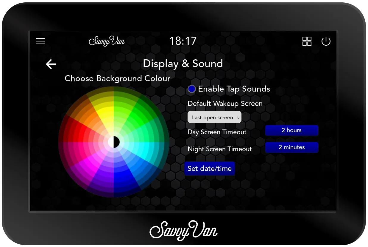
- Choose Background Colour - tap or drag on the wheel, and the panel changes colour as you go. It starts blue, and a very dark choice turns the buttons grey so they can still be seen. It saves when you leave the page.
- Enable Tap Sounds - a click on every tap. It starts on.
- Default Wakeup Screen - the screen the panel wakes up on. Last open screen, the default, is wherever it was left. Home is the main screen, and Brand is the converter’s own page on a panel built to a customer’s branding. With a battery the panel reads directly there is also Battery, and with SavvyTanks, Tanks. If the one chosen cannot open, it wakes on Home.
- Day Screen Timeout and Night Screen Timeout - how long without a touch before the screen sleeps. Day is 7am to 8pm, and night is the rest. They start at 2 hours and 2 minutes. Tap one, choose Seconds (1 to 600), Minutes (1 to 240) or Hours (1 to 24) and set the number with - and + - or choose Never - then tap Save.
- Set date/time - for a panel that will spend its life offline. Set the time and date with the arrows and tap Save. On WiFi the clock sets itself, and a panel that is online keeps the internet’s time instead.
The screen is the thirstiest part of the panel, so on a van that lives off-grid, keep the night timeout short. Sleeping the screen switches nothing off.
Troubleshooting
Everything above is the job when it goes to plan. If it has not, start here.
What a healthy start-up looks like
Watch it once - knowing the order turns a dead panel into a five-minute diagnosis. Shut it down properly (or, if it has stopped responding, pull the power), put the power back, and you should see:
- The green light comes on at the control board.
- The screen’s backlight lights up - no picture yet, just the screen waking.
- The SavvyVan logo.
- Black again for a few seconds. This is the part that catches people out. It has not crashed; it is still coming up.
- The main interface.
If it does not start
The two cables between the board and the screen do two different jobs, and that is what makes this quick to narrow down:
- USB brings the screen to life - backlight and touch.
- HDMI gives it something to show.
So a screen that lights up but shows nothing is a different fault from one that does nothing at all. Work down in order:
| What you see | What it is |
|---|---|
| No green light on the control board | No power getting to it. Check the fuse and the 12V feed first |
| Green light, but the backlight never comes on | The USB cable - unplugged at one end, or faulty |
| Backlight on, but the touch does nothing | A charge-only USB cable. It has power but no data lines - see cable lengths |
| Backlight on and touch works, but no picture | The HDMI cable |
| The logo appears, then it never reaches the interface | A fault we need to look at |
| 12V is present and a power cycle still gives no green light | A fault we need to look at |
The last two rows mean it comes back to us. That is not a fob-off - there is nothing useful left to try in the van, and the sooner it is with us the sooner you have it back. Start at report a fault, and send the log files from the passcode screen if the panel gets that far.
Everything else on that list is a cable or a fuse, and both are fixable where the van is standing.
If it starts but misbehaves, update it
The table above is for a panel that will not come up. Anything else - an odd reading, a page that will not load, a control that has stopped responding, something that worked last month and does not now - starts with an update.
Many reported faults are already fixed in a later release, and updating costs ten minutes against hours of fault-finding. The changelog lists what each version put right, so you can often spot your own symptom.
Settings → System Information → Update Now, on WiFi. The screen may be blank for up to 10 minutes while it works - leave it alone.
If the problem survives an update, tell us - and we will know it is not something we have already fixed.
If WiFi will not connect
If it will not connect or stay connected, the user guide has the full list - signal, mesh networks and iPhone hotspot quirks.
If a temperature sensor does not appear
Look in Additional settings first. A sensor that is listed there but set to None is working, and simply has not been given a place on the main screen yet.
If it is not listed there either, check the wiring and restart the panel.
If a scan finds nothing
A scan that finds nothing stays on Scanning … rather than saying so. Go back to the add-on and check its light: nearly always it is not powered, or not yet ready to pair. The light table in each add-on’s guide says which. Then leave the page, come back, and scan again.
Specification
| Supply | 12V and 24V systems, tolerant to 30V |
| Fuse | 2A, built in |
| Draw in operation | 0.1–0.3A at 12V |
| Operating temperature | −20°C to +60°C |
| Switches | 8, up to 10A each, positive or negative |
| Control board | 180 × 105 × 27 mm |
| Screen depth | 15 mm, plus 18 mm clearance behind |
| Screen profile | 1.2 mm visible when bonded |
| Cut-outs | 123 × 79 mm (5”), 166 × 102 mm (7”) |
| Screen to board | 2m supplied - HDMI to HDMI mini, and USB micro to USB micro. Longer cables are standard parts you can buy anywhere |
| Wireless | 2.4GHz 802.11 b/g/n, plus low-energy wireless for add-ons |
Where to go next
- SavvyVan3 user guide - living with it day to day, and what each screen means
- Register your device - adds a second year of warranty to the panel, free
- Fitting to a Sargent, CBE or BCA system? Those have their own guides, and the wiring is different.
Questions people ask
- Can I put the screen further than 2m from the board?
- Yes. The 2m cables in the box are standard parts - HDMI to HDMI mini, and USB micro to USB micro - so you can buy longer ones anywhere, or buy the ordinary HDMI and USB versions with an adapter on the end. The one thing that matters is that the USB cable carries data as well as power; a charge-only cable powers the screen and leaves the touch dead.
- Which cables do you recommend?
- We do not recommend a brand, because we have not tested them. Any decent cable of the right type works, and the only specification that matters is that the USB one is a data cable rather than charge-only.
- Can I take the screen off again once it is stuck down?
- No. The adhesive is designed to be permanent and the screen breaks if you try, which is not covered by warranty. The only removable option is the 7 inch screen on the bolted mounting plate.
- What voltage can it take?
- It runs on 12V and 24V systems and tolerates up to 30V, which gives headroom for the charging voltages a 24V system sees.
- Do I have to have WiFi?
- Only for the clock, the weather widget, updates and the App. Everything else works without it. Use the 2.4GHz band where you have the choice - it reaches further, and range is the limitation rather than speed.